Guides
How to build our Remixed GBA Slab SP
This guide will walk you through how to install our Remixed GBA Slab SP kit. This guide assumes you already have the appropriate soldering skills as well as all necessary parts / tools needed that don’t come with the kit.
Disclaimer: This guide was written for informational purposes only. We assume no liability or responsibility for damaged equipment or for any injury you may incur attempting to replicate this guide. If you damage a 3D printed part during the install, please reach out and we can do a direct sale for a new part. However, no free replacements will be given for damage caused by your installation.
This is a Remixed version of Xipher’s Gameboy SP Slab (V1). We also contributed to his V2 Slab with our bottom accessory port, battery nut area, and helped him troubleshoot issues like with his top back panel when used with the Game Boy camera. For posterity, here’s Xipher giving us permission to sell his Slab beyond the original “non-commercial” license.
What you’ll need
- FunnyPlaying IPS Screen for the GBA SP
- Humble Bazooka’s GBA Slab SP Remixed Shell
- Humble Bazooka’s Button PCB
- GBA SP motherboard
- GBA SP Screws or similar
- GBA SP Battery (I use Helder’s)
- GBA SP battery door nut and screw (required)
- FFC / FPC 100mm Cable and Extender board
- Game Boy Pocket D-Pad, Buttons, and membranes
Tools you’ll need
- Soldering iron
- Solder (Kester is great)
- Flush cutters
- Tri-Wing Screwdriver
- Philips Screwdriver
- 30-gauge wire or magnet wire
- Kapton Tape
- Super Glue (optional)
Table of Contents
- Prepping the Rear Shell
- Installing the L and R Buttons
- Installing the Light Pipping
- Installing the Soft Tactile Buttons
- Buttons, PCB, and Speaker
- Wiring the Button PCB and Motherboard
- Installing the Screen
- Installing the Flex Cable
- Finishing Up
1. Prepping the Rear Shell
In this section, you will need the original GBA SP battery door nut and screw (these are mandatory), metal cartridge shield, power switch, and the following 3D printed parts: back shell, battery bay, and cartridge brace.
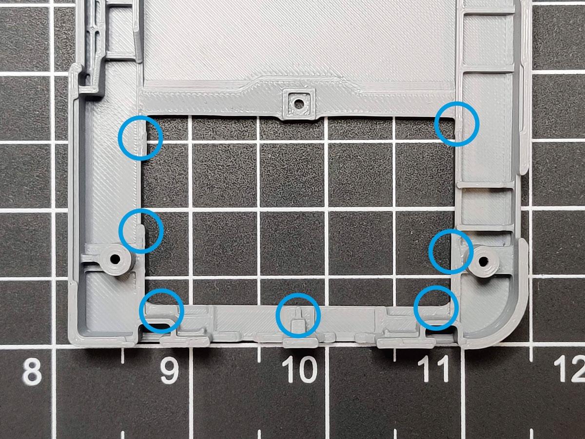


- Optional: Apply a small amount of glue to the circled areas of the back shell.
- Take the 3D printed cartridge brace and lay it down on the lower shell in the same orientation of in the photo. No glue is needed.
- Screw down the GBA SP’s metal cartridge shield on top of the cartridge brace using the original screws from the GBA SP shell.
- Take you GBA SP’s battery door nut and put it in place.
- Tip: To keep it in place, secure it with the original GBA SP cart door screw.
- This is also a good time to place the GBA SP power switch into the bottom shell, so you don’t forget later.
2. Installing the L & R Buttons
In this section, you will need a hobby knife, the back shell, L and R buttons.


- The 3D printed L & R buttons may already be installed when you get your kit. If this is the case, you can skip this section.
- Take one of the shoulder buttons and example it. You will notice it has two protrusions on the inner “peg”. These will help hold the buttons in the shell. In the next steps you’ll be shaving down the sides of these buttons. Do not cut off these protrusions!
- Take you hobby knife and shave down some of the plastic on all 4 sides of the shoulder button peg. The idea here is you want to remove the layer lines a bit, so that the button slides in and out of the back shell smoother.
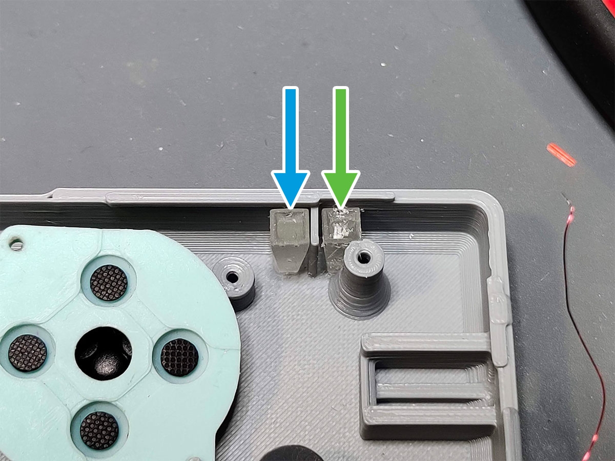
- While working on the next steps in this section, be mindful of this delicate part on the back shell. However, If you break it off it’s not the end of the world.
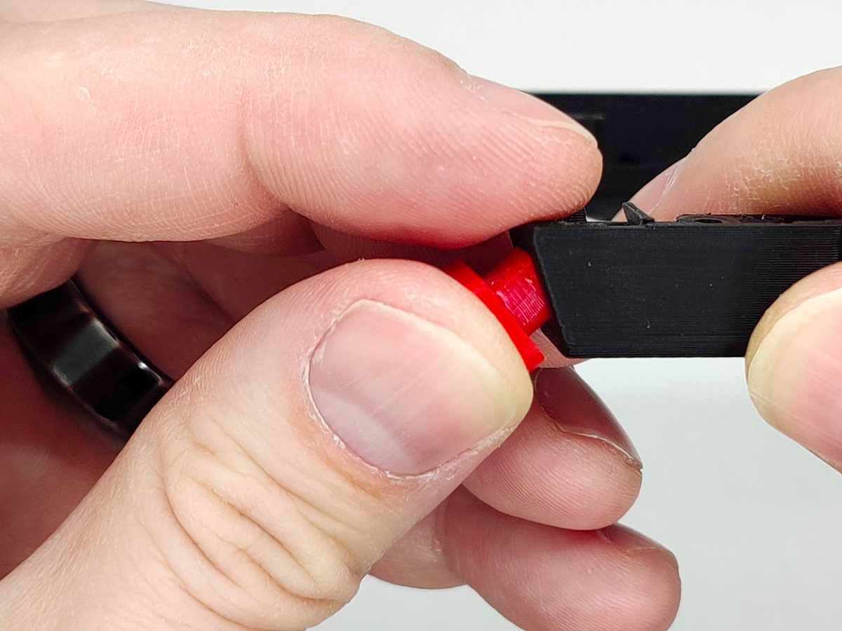
- Once you’ve shaved down the shoulder button’s peg, take the back shell and insert the shoulder button in an angle, bottom first.
- While firmly holding the lower shell, but being mindful not to bend or damage it, push the shoulder button into the back shell with most of the force at the top of the button.
- Repeat these steps for the other shoulder button.
3. Installing the Light Pipping
For this section, you will need the resin printed light pipping and front shell.
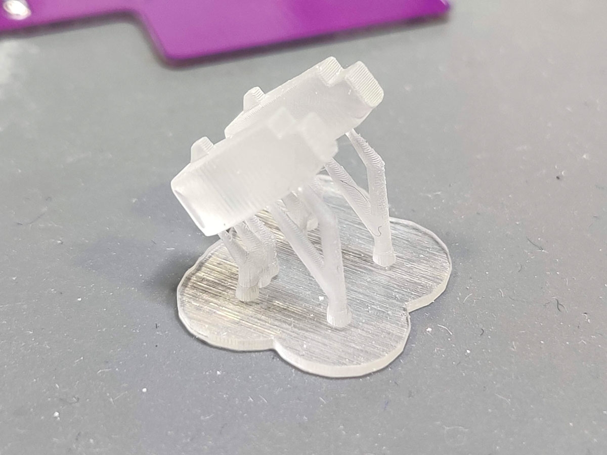

- Your GBA Slab SP kit’s light pipes will most likely come attached to their resin supports.
- To start, break the light pipes off of their supports. They’re pretty sturdy, so nothing should break.
- Both light pipes are universal, so it doesn’t matter which side of the front shell you install them on. I always start from the right light pipe opening because the left light pipe will probably come loose while moving the front shell around.
- Starting with the right side light pipe, carefully apply gentle force and push it into its opening between the screw post and wall of the front shell. Try not to scuff it up too much in the process like I did on my demo unit.
- Once the right post is installed, drop the left post into place. This doesn’t require any force.
- If the left light pipe keeps, use some tape to hold it in place. Later, the motherboard itself will do the job.
4. Installing the Soft Tactile Buttons
In this section, you will need the 2 soft tactile buttons, thin wire, and back shell you prepared in the previous step.


- Take the soft tactile buttons included with the kit and snip off two of the legs on the same side of each button. Now, tin the remaining two legs with some solder.
- Cut four pieces of thin wire about 3″ long, or as long enough to reach the bottom of the shell at a diagonal from where the should buttons will be installed. Tin the wires and solder them to the two legs on each tactile button.
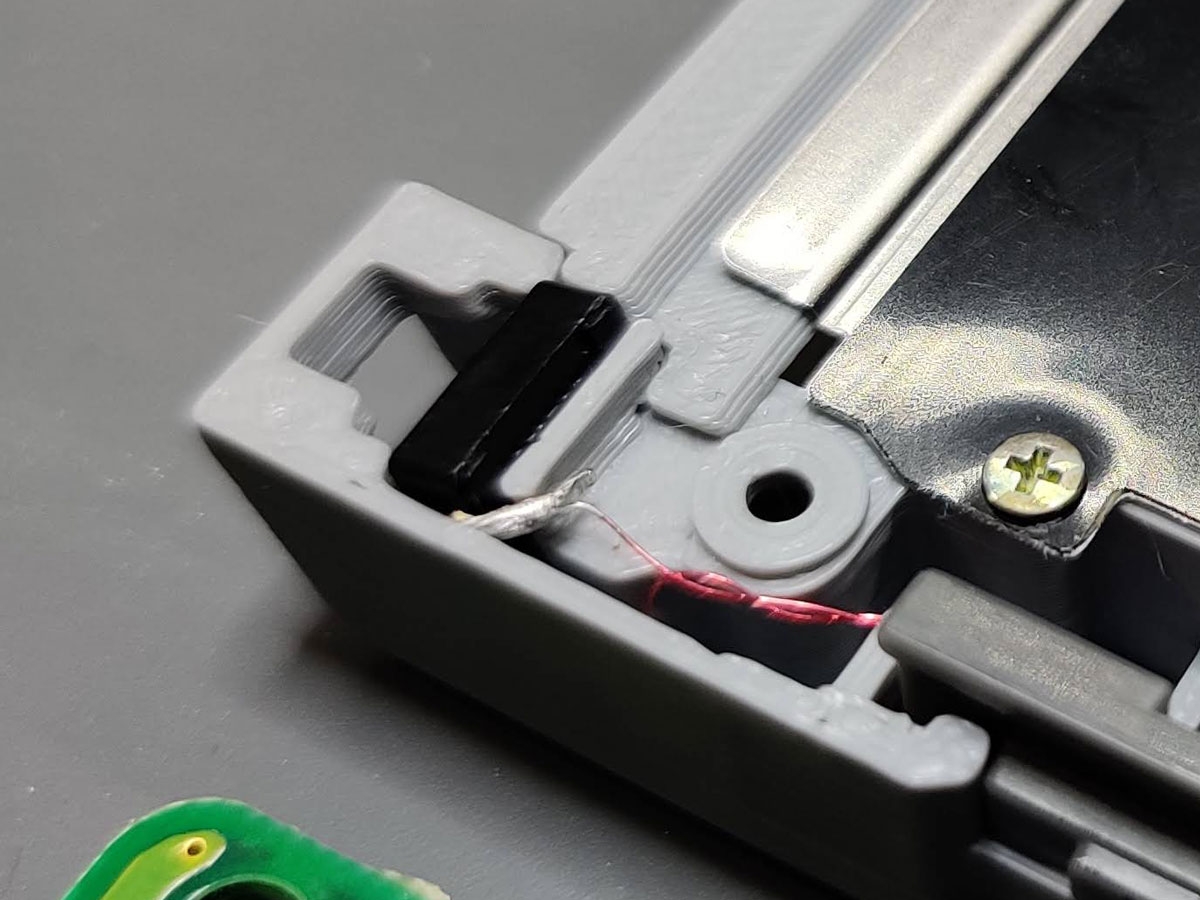
- Now insert the L & R soft tactile buttons into the lower shell with each sides legs facing outward towards the sides of the shell.
- Next, get an idea of how you want to run the wires. I ran them under the mother board. For example, the new “L” shoulder button will wire to the bottom right tactile button on the GBA SP motherboard. Just make sure you leave enough slack in the wire.
- Remember that the soft tactile buttons are mirrored since the motherboard is now flipped.
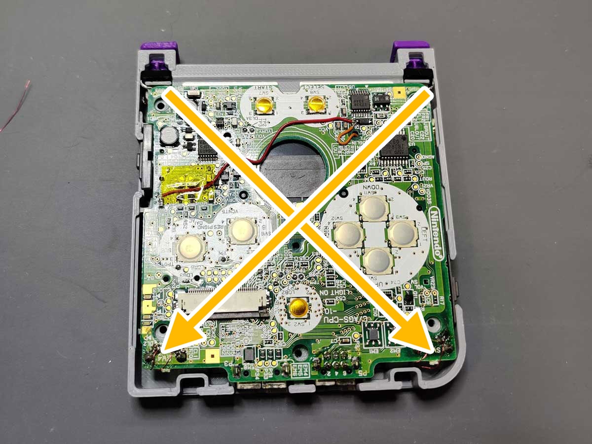
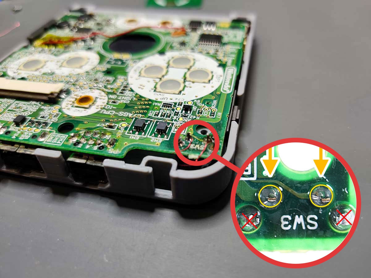
- Put the GBA motherboard (MoBo) into the lower shell and rout the L & R wires how you want them. Tweezers come in handy here if running under the MoBo. Solder each soft tactile button’s wires to the existing GBA SP button legs circled in yellow. It doesn’t matter which wire goes to which existing pin on the GBA Motherboard.
5. Button PCB and Speaker
For this section you will need the hard tactile button, Button PCB, D-Pad, face buttons, button membranes, speaker, thin wire, and the following 3D printed parts: font shell, speaker brace, and brightness button.


- Tin the Button PCB pads and the speaker’s pads, being careful not to heat the speaker too much.
- Cut two small pieces of wire about an inch long, tin and solder a wire to each speaker pad. Insert the speaker into the front shell.
- Insert the hard tactile button into the Button PCB and bend the pins to hold it into place. Don’t solder it in just yet, we’ll do that later once it’s perfectly aligned in the shell.
- Add the D-Pad, A, B, brightness button, Select and Start buttons, and the remaining button membranes to the front shell.
- Take the Button PCB with the hard tactile button inserted into it and screw it into the front shell.
- You can now solder the hard tactile button down and clip the legs using flush cutters.
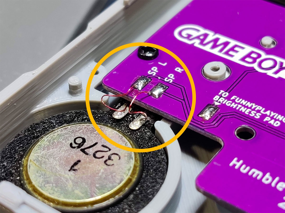
- Solder the speaker wires to the “SP L” and “SP R” pads on the Button PCB.
- Place the 3D Printed speaker brace over its two pegs and push down. There are two optional screw holes for M1.7 x 5mm screws.
6. Wiring Up the Button PCB and GBA SP Motherboard
In this section, you will need some thin wire and the populated front and back shell from the previous steps.


- This is the hardest part of the build. If you’re not confident at soldering small test pads, take some time to practice before continuing.
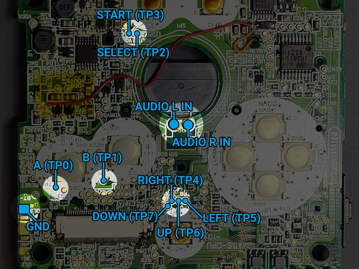
- You’ll be soldering to the right most button PCB pads with all the button and audio signals.
- When soldering to the button PCB, be careful not to melt the GBA Slab SP shell with your iron.
- Lay out the GBA Slab SP front and back shells, from left to right. This will help with wire management and to get a good idea of how long your wires should be.
- For the next step, be careful not to damage or lift the LED that’s close to this ground pad.
- Time to solder. Starting with the “A” button, solder a thin piece of wire from the A button test pad (TP0) to the “A” pad on the button PCB. Do this for every GBA test pad outlined in the photo and try to do some wire management as you go. It will help when you close the GBA Slab SP up later.
- Tip: wrap the wire you’re working on around the other wires as you solder to each pad. This will help contain the rats nest .
- Tip: It’s a good idea to test connections between the button PCB and MoBo with a multimeter. Doing it now may save you from having to take apart the GBA Slab SP down the road.
7. Installing the FunnyPlaying Screen
In this section, you’ll need the FunnyPlaying IPS screen, flex driver cable, thin wire, and front shell.


- Start by tinning the IPS screen flex cable’s brightness pad. Solder a thin piece of wire a few inches long to the brightness pad.
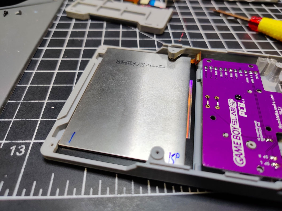
- Sliding just the FunnyPlaying screen into the top shell at an angle.
- Make sure the IPS screen connector clears the screw post before applying too much force on the screen.
- The screen should sit flush with the shell.
- Now take the IPS flex driver board and slide it under the right screw post of the front shell. This will place it at the bottom right of the IPS screen.
- If you have issues sliding the driver flex cable under the screw post, remove the screen and shave the bottom of the screw post of any hanging plastic. This is an “overhang” area that gets printed on top of supports.
- Line up the flex driver board with the IPS screen’s connector and push down to seat the connector to the flex board.
- Tip: use some Kapton to hold the flex driver board in place against the back of the IPS screen.
- Solder the flex cables brightness wire to the button PCB board. Optionally, apply some Kapton tape to hole the board in place.
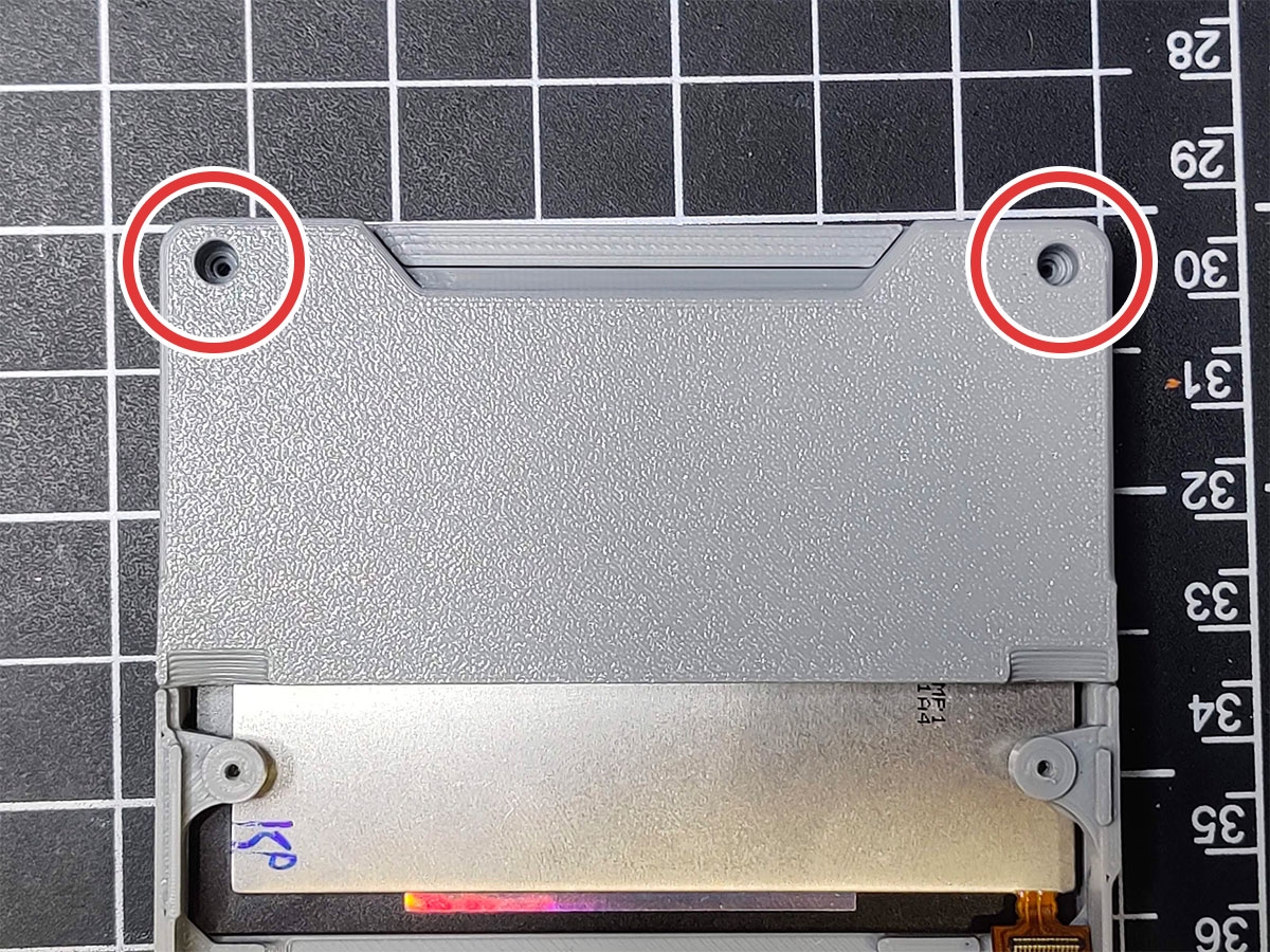
- Lastly, take the top back 3D printed shell and screw it down on top of the the front shell with screws no longer than 4mm long.
- Tip: cut a piece of the original GBA SP’s screen foam and put it above the IPS screen driver board. This will help the screen from jiggling in the GBA Slab SP shell.
8. Installing the Flex Cable
For this section, you will need both front and back populated shells, 100mm 34-pin flex cable, 40-pin extender board, thin wire, and the top back 3D printed shell.
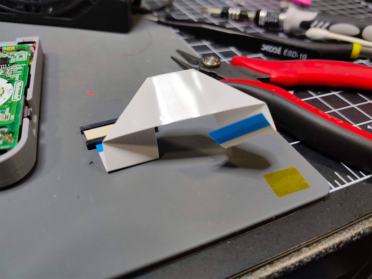


- This is probably the most finicky of parts to this project because it involves some cable origami. Bend your 100mm 34-pin flex cable in the same way shown in the photo.
- Next, take the extension board and attach the IPS screen flex and the 100mm 34-pin cable in the orientation shown.
- Make sure both the IPS screen flex cable and 34-pin cable are both aligned at the same starting point on the extender. The idea here is you want the pins to passthrough from one cable to the other.
- Tip: use a multimeter to test to make sure pins on both cables test properly for continuity.
- Time to connect the origami 100mm 34-pin flex cable to the GBA SP motherboard. Make sure the GBA SP pin connector is slide out, allowing you to insert the 34-pin cable. Make sure the pins of the cable are facing up.
- Moment of truth. If your wire management was good and you’ve been Kapton taping things as you go, the two halves of your GBA Slab SP should fold together nicely.
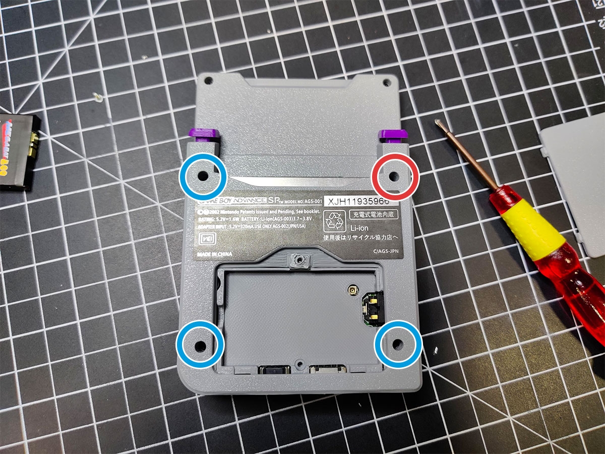
- Use 4 screws to secure the back of the GBA Slab SP to the front shell.
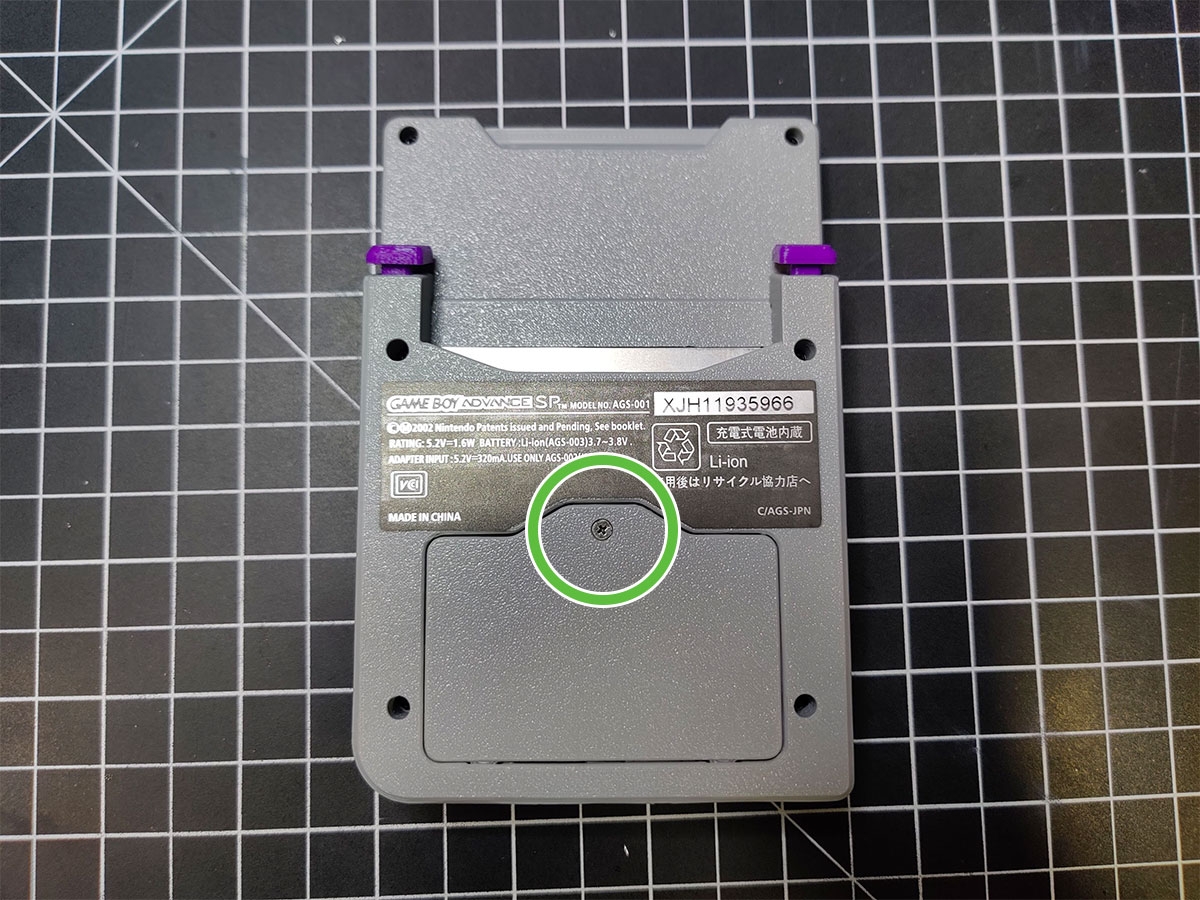
- If you used the original battery door screw to hold the nut in place, remove it and add the battery.
- Put the battery door back in place and screw it down with the battery door screw.
- Congratulations, you’ve built a GBA Slab SP!
9. Finishing up
You’re in the home stretch. You will need the almost finished GBA Slab SP, 4 screws (original GBA SP or M2 x 6mm), battery (I highly suggest Helder’s “MegaBat800“), battery door screw, and 3D printed battery door.


- If your wire management was good and you’ve been Kapton taping things as you go, the two halves of your GBA Slab SP should fold together nicely.
- Use 4 screws to secure the back of the GBA Slab SP to the front shell.
- Just a reminder that the top right screw’s length shouldn’t exceed 6mm.
- If you used the original battery door screw to hold the nut in place, remove it and add the battery.
- Put the battery door back in place and screw it down with the battery door screw.
- Congratulations, you’ve built a GBA Slab SP!